Welcome to Section_7
Paul Stewart 5/17/2016
See this sections QnA
See schematic symbols
See this section's first training video
See this section's second tranining video
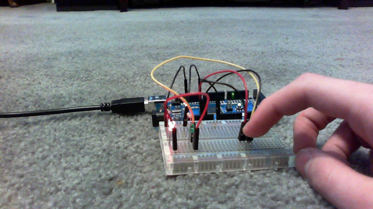
Project 4 - Demonstrating_a_Digital_Input
The goal of this project was when the button was pressed, it would turn on
the LED for half of a second. the picture below shows me pressing the
button to turn on the LED. The code and the wiring used to run this
progam were relatively simple.
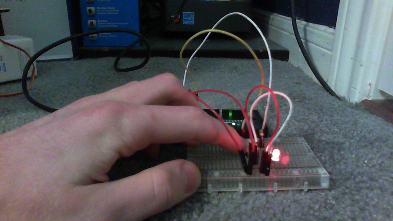
Project 5 - Controlling_traffic
Our goal is to install three-color traffic lights at each end of the
single-land bridge. The lights allow traffic to flow only in one direction
at a time. when sensors located at either end of the bridge detect a car
waiting at a red light, the lights will change and allow the traffic to
flow in the opposite direction. This code repeated alot of the same pieces
of code many times, such as the sequence to change to the opposite side of
the intersection. The wiring was complicated, and figuring out which way
to put the buttons was a little tricky.
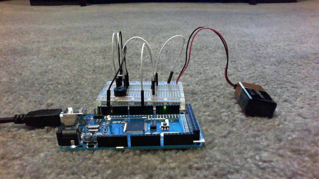
Project 7 - Trying_out_a_Piezo_Resistor
The purpose of this project was to create a circuit in which a piezo (buzzer)
would buzz for half a second, then turn off for another half second. This
code looks relatively simple, but it operates wiring which took little bit of
work to get done, like the Controlling_traffic project.
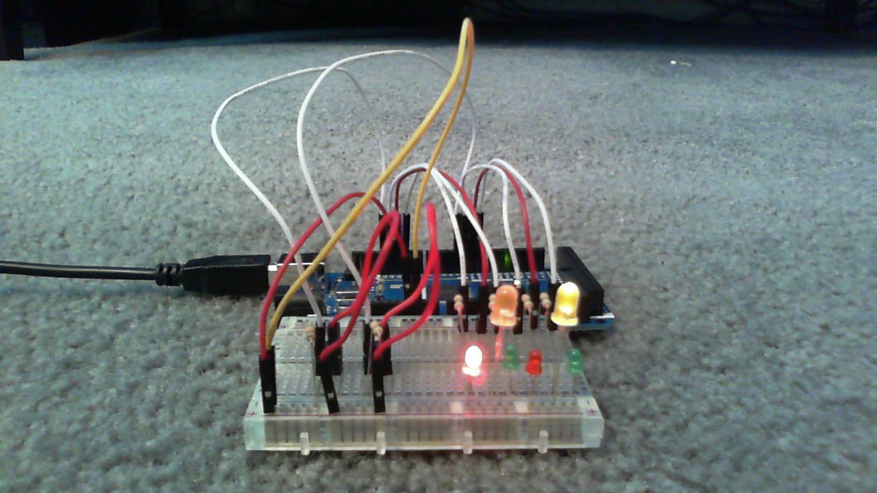
Project 8 - Creating_a_quickread_ thermometer
This project was a fun project. It alternated between two light colors based on
temperature. It is mostely on the red light because the temperature around here
is usually higher than 75 degrees, the cold to hot boundary. If the temperature
was less than or equal to 75, the light was green. If it was more than or equal
to, it red. The best way to make the temperature lower than 75 degrees is to
an ice cube to the temperature sensor.